
Electronics fail for predictable reasons: heat buildup, poor grounding, and mechanical stress. Many PCB projects work in the lab but fail in real-world use because the enclosure was an afterthought. That mistake leads to overheating, EMI interference, and costly redesigns.
If you want a reliable product, you must design the aluminum PCB enclosure as part of the system—not as a box around it. This guide walks you step by step through material selection, manufacturing methods, thermal design, and OEM production planning.
What an Aluminum PCB Enclosure Is and Why It’s Used
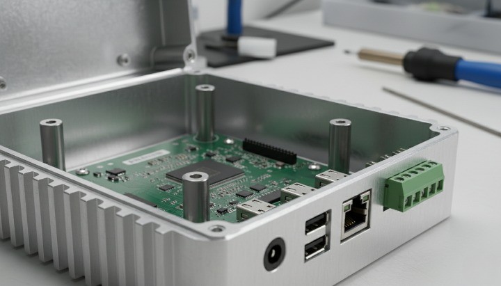
An aluminum PCB enclosure is a protective housing made from aluminum alloy that holds and protects a printed circuit board while improving heat dissipation, EMI shielding, and structural durability.
Compared to plastic, aluminum provides:
- High thermal conductivity (≈205 W/m·K for 6063 alloy per MatWeb)
- Natural EMI shielding
- High strength-to-weight ratio
- Corrosion resistance after anodizing
- Long service life in industrial environments
According to the International Aluminum Institute, aluminum remains one of the most widely used industrial metals due to its recyclability and durability. For electronics, it adds both protection and thermal performance.
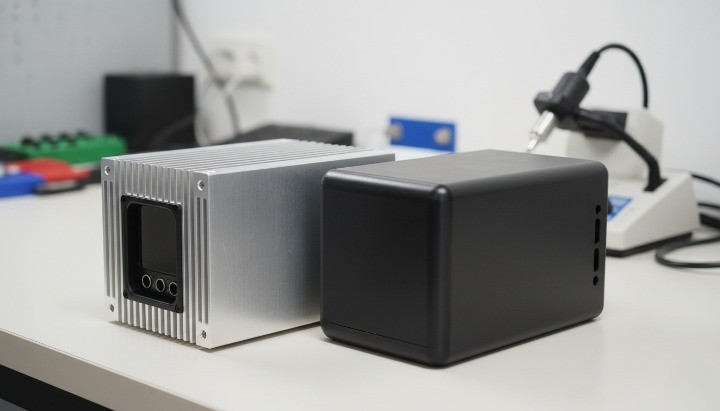
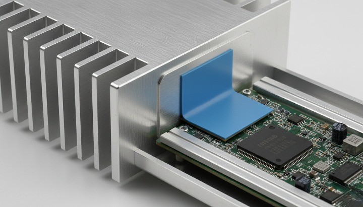
!Aluminum PCB enclosure extruded housing with PCB installed and heat sink fins
Step 1 – Define PCB and Mechanical Requirements
Before selecting material or manufacturing method, define the mechanical framework.
Key parameters:
- PCB length, width, thickness
- Mounting method (standoff, slide-in slot, rail guide)
- Clearance tolerance (typically 0.2–0.5 mm for slide-fit designs)
- Connector positions
- Cable exit direction
- Required IP rating
- Operating temperature range
If your device must pass CE or FCC testing, enclosure grounding design directly impacts EMI compliance.
For industrial applications, always consider:
- Vibration exposure
- Outdoor UV exposure
- Moisture risk
- Thermal expansion
Aluminum expands at about 23 µm/m·°C. Ignoring this can cause stress at mounting points.
Step 2 – Choose the Right Aluminum Alloy
Different alloys serve different manufacturing paths.
Common Aluminum Alloys for PCB Enclosures
| Alloy | Strength | Thermal Conductivity | Typical Use |
|---|---|---|---|
| 6063 | Medium | High | Extruded enclosure profiles |
| 6061 | Higher | Moderate | CNC machined housings |
| 5052 | Sheet strength | Moderate | Bent sheet enclosures |
6063 is ideal for extrusions because of its smooth surface finish and good anodizing response.
6061 offers higher strength for CNC machining.
Material properties can be verified via ASM International.
Choose alloy based on:
- Production volume
- Required strength
- Machining complexity
- Surface finish expectations
Step 3 – Select Manufacturing Method
The manufacturing path determines cost structure, MOQ, and lead time.
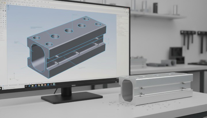
1. Extruded Aluminum PCB Enclosure
Best for long-profile housings with consistent cross-sections.
Process:
- Custom extrusion die (2–4 weeks tooling)
- Profile extrusion
- Cutting to length
- CNC machining for holes
- Surface treatment
Advantages:
- Low per-unit cost at volume
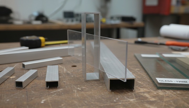
- Integrated PCB sliding grooves
- Good heat dissipation
Consideration:
- Initial die cost
- MOQ typically required
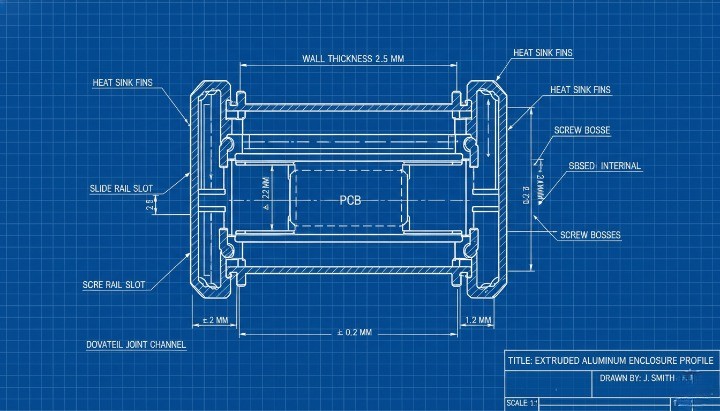
!Extruded aluminum PCB enclosure profile cross section with slide rails
2. CNC Machined Aluminum Housing
Best for:
- Low-volume production
- Complex geometries
- Thick base heat sink integration
Advantages:
- No extrusion tooling
- Flexible prototyping
- High precision
Limitation:
- Higher cost per piece
- Longer machining time
3. Sheet Metal Fabrication
Uses 5052 sheet, bending, and welding.
Suitable for:
- Larger boxes
- Lower thermal demand products
- Fast production without extrusion die
Step 4 – Thermal Management and EMI Design
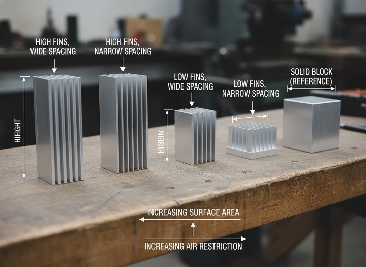
Aluminum enclosures act as passive heat sinks.
Thermal design considerations:
- Increase wall thickness for heat spreading
- Integrate external fins
- Use thermal pads between PCB and enclosure
- Position heat-generating components near enclosure walls
According to Electronics Cooling Magazine, enclosure material significantly affects system thermal performance.
EMI control methods:
- Ensure enclosure grounding continuity
- Use conductive gaskets for removable covers
- Avoid large slot openings
- Maintain metal-to-metal contact at joints
Proper grounding ensures shielding effectiveness.
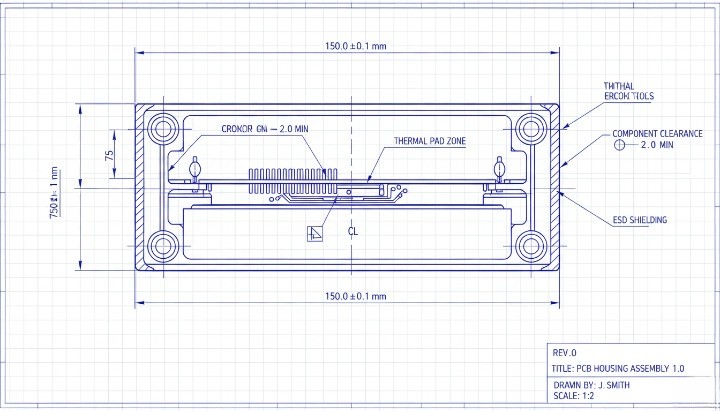
!Aluminum PCB enclosure with integrated heat sink fins and thermal pad contact
Step 5 – Surface Finishing and Corrosion Protection
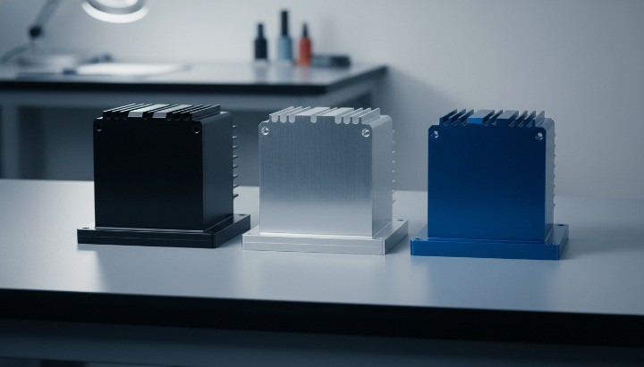
Surface treatment impacts durability and appearance.
Common Finishes
- Anodizing (5–25 μm thickness)
- Powder coating
- Sandblasting
- Brushing
Anodizing increases corrosion resistance and electrical insulation on surface layers.
Typical anodizing thickness for electronics: 10–15 μm.
For outdoor applications, consider salt spray testing per ASTM B117 standard.
Step 6 – Prototyping and Testing
Before mass production:
- Produce CNC prototype
- Perform fit verification
- Conduct thermal testing
- Check EMI performance
- Validate surface finish
Testing tools may include:
- Thermal chamber
- Salt spray test
- Hardness tester
- Spectrometer for alloy verification
Prototype stage prevents tooling errors in extrusion projects.
Step 7 – Mass Production and OEM Strategy
For extrusion-based aluminum PCB enclosures:
- Die lead time: 2–4 weeks
- Sample approval: 1 week
- Mass production: 2–3 weeks
Typical MOQ varies by profile complexity and finishing requirement.
Production flow:
- Extrusion
- Aging treatment
- CNC machining
- Surface finishing
- Inspection
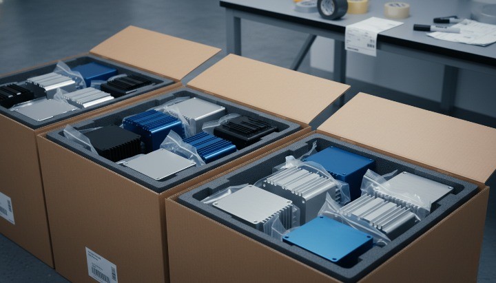
- Packaging
Export considerations:
- Foam protection
- Carton reinforcement
- Sea vs air freight choice
For global buyers, confirm compliance with RoHS and REACH directives.
Cost Breakdown Factors
| Cost Factor | Impact Level |
|---|---|
| Tooling (Extrusion Die) | High (initial) |
| Alloy Selection | Medium |
| CNC Machining Time | High |
| Surface Treatment | Medium |
| MOQ | High |
| Packaging & Shipping | Medium |
Volume production reduces per-unit cost significantly in extrusion projects.
Common Design Mistakes to Avoid
- Ignoring thermal expansion
- Overly tight slide-fit tolerances
- Using 6061 for extrusion-only profile
- Poor grounding continuity
- Designing without assembly clearance
A well-designed enclosure reduces assembly time and warranty risk.
FAQ
How thick should an aluminum PCB enclosure be?
Typical wall thickness ranges from 1.5 mm to 3 mm depending on structural and thermal requirements.
Is aluminum better than plastic for PCB enclosures?
Yes, when heat dissipation and EMI shielding are required.
What is typical MOQ for extruded aluminum enclosures?
MOQ depends on profile size and finish. Many suppliers require batch production after die creation.
How long does it take to manufacture a custom aluminum enclosure?
From design to mass production, usually 4–8 weeks including tooling.
Design Smart, Manufacture Efficiently
An aluminum PCB enclosure is more than a protective shell. It controls heat, improves signal stability, and extends product life. When you align alloy selection, manufacturing method, and thermal design from the beginning, you reduce cost and improve reliability.
Make enclosure design part of your engineering process—not an afterthought.
Start Your Custom Aluminum PCB Enclosure Project
If you are developing a new electronic product, share your PCB drawing and mechanical requirements.
Our team supports:
- Custom extrusion profiles
- CNC machining
- Anodizing and finishing
- OEM production planning
- Export packaging
Send your drawings for evaluation and receive a technical quotation.