
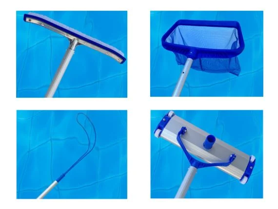
A durable telescopic pole is not created by one alloy or one thick tube. It stays usable because the aluminum sections, overlap, locks, connectors and plastic parts are matched to the intended reach and working load.
This is also why “does not break” should not be treated as an unconditional product promise. Any pole can bend or fail if it is overloaded, used with the wrong attachment or damaged in service. The practical engineering goal is to reduce predictable failure risks and define a pole that can be tested against its actual application.
Why Telescopic Poles Bend or Break
A failure usually begins with a mismatch between the product structure and the way it is used. The visible break may occur in the aluminum tube, but the underlying cause can be excessive reach, insufficient overlap, a slipping lock or an attachment that creates more leverage than the pole was designed to carry.
Common causes include:
- Excessive working force: a vacuum head, wet brush or loaded rake can create much more resistance than a lightweight skimmer net.
- Too much extension: extending every section increases leverage and deflection.
- Insufficient tube structure: diameter, wall thickness, alloy and temper may not suit the required reach and attachment.
- Short or inconsistent overlap: stress becomes concentrated near the telescoping joint.
- Loose section clearance: movement at the joints increases instability and uneven loading.
- Lock slip: a section that moves unexpectedly can create shock loading or reduce overlap.
- Local dents or drilled features: damaged or poorly processed areas can become stress concentrations.
- Impact and misuse: dropping, crushing, levering sideways or using the pole near unsupported obstacles can exceed its intended duty.
Preventing these problems starts with defining the tool, reach and working resistance before choosing a tube.
1. Choose the Aluminum Tube for the Real Application
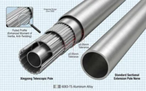
6063-series aluminum is commonly used for extruded pole and tube programs because it offers a useful combination of extrudability, surface finish, weight and mechanical performance. ASTM B221, the specification for aluminum-alloy extruded tubes and profiles, can be used to define material and mechanical-property requirements. However, compliance with a material specification alone does not determine whether a finished pole is suitable for a task; reach, section geometry, locks, connectors and the defined load test still control product performance.
The tube design also includes:
- outside diameter;
- wall thickness;
- alloy and temper;
- section length and number of sections;
- changes in diameter between nested tubes;
- holes, slots, threads and other processed features;
- surface treatment and final assembly.
A thicker wall can improve stiffness or dent resistance, but it adds weight and changes section fit, lock matching and cost. Increasing diameter may improve stiffness more efficiently in some designs, but it also affects grip size, connectors and collapsed dimensions. The correct combination is selected around the intended product, not a universal “heavy-duty” number.
OEM buyers should record the agreed material and tube dimensions on the approved specification. Xingyong reviews these variables together when developing a custom aluminum telescopic pole.
2. Use Section Overlap to Support the Joints
A telescopic pole is most vulnerable where one tube transfers load into the next. Adequate engagement distributes the force through the joint; insufficient overlap can make the pole feel loose and increase local stress.
The overlap requirement depends on tube diameter, wall, section length, lock position and expected load. It should be controlled by the product design and stop features rather than left entirely to user judgment.
During sampling, check the pole in the positions that matter:
- fully collapsed for storage and shipping;
- partly extended for common working reach;
- fully extended with every lock engaged;
- loaded with the intended tool attached;
- after repeated extension and retraction.
Adding more sections can shorten the packed product, but every additional joint introduces another tube fit and lock interface. Long reach, compact storage and rigidity therefore need to be balanced rather than maximized independently.
3. Match the Lock to the Tube and Working Force
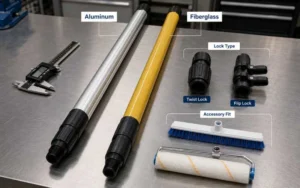
A strong tube cannot deliver stable performance if the lock slips. Twist, flip and push-button locks use different mechanisms, and each must be matched to the tube dimensions, surface and operating conditions.
A lock review should include:
- positive engagement and release;
- holding under the intended axial force;
- resistance to rotation where the tool creates torque;
- operation with wet or gloved hands when relevant;
- slip after repeated cycles;
- wear, cracking or loosening of plastic parts;
- consistent assembly across production batches.
Surface finish can also change the interaction between the tube and lock. The finished production tube—not only an unfinished prototype—should therefore be used for final validation. See the twist-lock versus flip-lock guide for the main selection trade-offs.
4. Reinforce the Connector and Load Path
The attachment determines how force enters the pole. A skimmer net mainly carries light surface debris, while a pool brush creates side force and a vacuum head creates continuous underwater push-pull resistance. Threaded tools, clips, cones and custom connectors also transfer load differently.
The connector, fastener and surrounding tube should be reviewed as one load path. Checks can include:
- fit with the buyer’s actual tool sample;
- hole or thread position and edge condition;
- resistance to loosening or rotation;
- local tube deformation around the connection;
- clearance during packing and shipping;
- function after the agreed load test.
A reinforced connector does not compensate for an underspecified pole, and a strong pole does not protect a weak connector. Both need to be approved in the same assembled sample.
5. Select Plastic Parts for Outdoor Use
Locks, grips, end caps and connectors can be exposed to sunlight, moisture, pool chemicals and repeated handling. Resin type, UV stabilization, wall design and assembly stress influence whether these parts retain their fit and function.
ABS and other engineering plastics can be appropriate for specific components, but “new material” or “anti-UV” is not by itself a complete durability specification. Buyers should define the environment and confirm the finished component through agreed checks, which may include:
- visual inspection for molding defects;
- fit and retention on the aluminum tube;
- lock engagement and release;
- impact or functional handling appropriate to the part;
- exposure or weathering requirements for the target market;
- inspection after repeated pole operation.
Sharp corners, excessive press fit and overtightened fasteners can introduce assembly stress even when the resin is suitable. Component geometry and assembly method therefore remain part of the durability review.
6. Evaluate Bending and Deflection with a Defined Test
A statement such as “supports 10 kg” is not meaningful without the test setup. The same pole can produce very different results depending on extension length, support position, load direction, attachment and measurement method.
A useful evaluation records:
- Pole configuration: number of sections, overlap, lock and connector.
- Extension: the actual working length used during the test.
- Support and loading point: where the pole is held and where force is applied.
- Load direction: horizontal bending, axial pull, rotation or representative push-pull use.
- Acceptance criteria: allowable deflection, lock slip, permanent deformation and component damage.
- Post-test function: extension, retraction, locking and attachment fit after unloading.
The allowable values should be agreed for each model. The telescopic pole load-capacity guide explains the engineering variables; the telescopic pole durability and quality-testing guide covers the wider production-control plan.
7. Control the Manufacturing Details That Create Weak Points
Even a sound design can become inconsistent if tube dimensions, holes, edges or assembly vary. Production controls should focus on the features that transfer load or affect movement.
| Area | What to check | Failure risk reduced |
|---|---|---|
| Aluminum tube | Material, diameter, wall, straightness and roundness | Excessive bending, poor fit or local weakness |
| Telescoping sections | Clearance, overlap, stops and movement | Wobble, binding or joint instability |
| Deep processing | Hole position, slots, threads, cut ends and deburring | Stress concentration, cracking or assembly damage |
| Locks | Fit, holding, slip and repeated operation | Unexpected section movement |
| Connectors | Tool fit, retention and local tube condition | Loose or broken attachments |
| Plastic parts | Material, molding, fit and assembly stress | Cracking, loosening or poor operation |
| Finished pole | Alignment, extension, function and agreed load test | Batch-to-batch performance variation |
When repeatability matters, the approved sample should be supported by a written specification and inspection criteria. A visual sample alone cannot define internal tube dimensions, load configuration or acceptable lock slip.
8. Recognize the Difference Between Deflection and Failure
All long poles deflect under load. Deflection does not automatically mean the product has failed, and a pole that looks rigid is not automatically safe for every task. The acceptable amount depends on user control, attachment function and whether the pole returns to its original condition after unloading.
| Observation | What it may indicate | What to check next |
|---|---|---|
| Temporary bowing under load | Normal elastic deflection or insufficient stiffness for the application | Measure deflection and confirm user-control criteria |
| Permanent bend after unloading | Load exceeded the structure or a local weak point formed | Tube design, dents, holes, overlap and loading condition |
| Sudden loss of reach | Lock slip or incomplete engagement | Lock assembly, tube dimensions and holding test |
| Crack near a hole or connector | Stress concentration, processing damage or unsuitable load path | Hole geometry, deburring, fastener and connector design |
| Loose or broken plastic part | Impact, resin, geometry, UV exposure or assembly stress | Component specification and finished-part test |
This distinction helps buyers set realistic acceptance criteria instead of asking for a pole that shows no movement at full reach.
9. How Buyers Can Specify a More Durable Telescopic Pole
Include the following information in the RFQ:
- application and actual tool attachment;
- working and collapsed length;
- preferred number of sections;
- expected push, pull, bending or rotational force;
- current tube dimensions if replacing an existing product;
- lock and connector preference;
- acceptable weight and handling requirement;
- poolside, marine, outdoor or chemical exposure;
- finish, color, branding and packaging;
- required sample, load or cycle test;
- order quantity and target market.
If a current pole has failed, send the complete sample and explain the attachment, extension and force being used when the problem occurred. The location and shape of the damage can help distinguish overload, impact, lock slip, local processing weakness and unsuitable section design.
Frequently Asked Questions
Does 6063-T5 aluminum guarantee that a telescopic pole will not break?
No. Alloy and temper are only part of the specification. Diameter, wall thickness, section overlap, reach, lock, connector, processing and working load determine the behavior of the finished pole.
Is the thickest wall always the best choice?
No. A thicker wall can add stiffness and dent resistance, but it also increases weight and cost and may affect section fit. The structure should meet the application without making the pole unnecessarily heavy.
Why does a pool pole bend more when fully extended?
Greater extension increases leverage and exposes more joints. The pole can therefore show more deflection at full reach even under the same attachment load.
Which pool-cleaning tool creates the highest load?
It depends on use, but vacuum heads, loaded leaf rakes and brushes can create greater continuous or side resistance than a lightweight skimmer net. The actual tool should be used when confirming the specification.
Can a damaged aluminum pole be straightened and reused?
A permanently bent, dented or cracked structural section may have reduced capacity and should not be assumed safe after straightening. Replace the damaged section or pole according to the supplier’s guidance.
What evidence should an OEM buyer request?
Request an approved specification, production-representative sample, defined load or functional test, inspection criteria and batch records appropriate to the order.
Design Around the Actual Load
Develop a Telescopic Pole with Measurable Durability
Share the tool, reach, working force, failed sample or target specification. Xingyong can review the tube, overlap, lock and connector before sampling.
Explore custom telescopic pole manufacturing · Send your durability RFQ


 English
  Español
  Français
  Deutsch
  Português