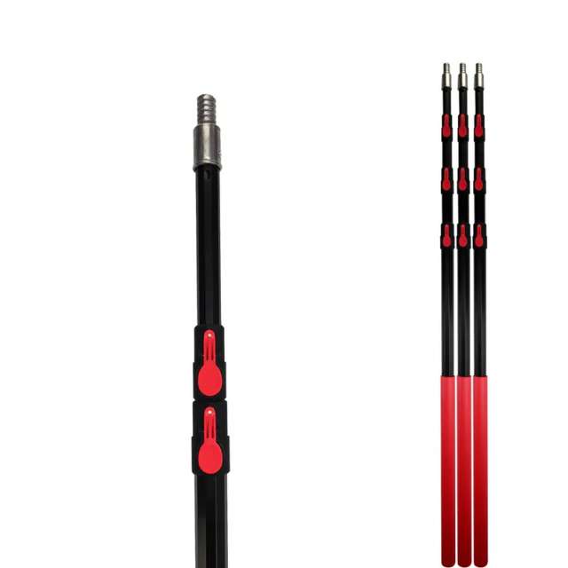
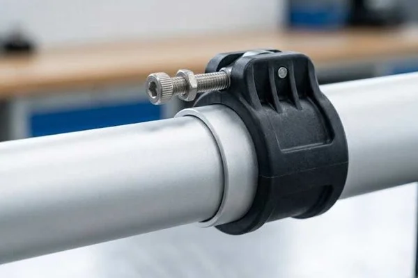
Single Button Lock
Positive locking at defined positions for simple repeatable setup.

OEM Spec Sheet · Push-Button Lock
The push-button build sheet: button and spring spec, hole positioning, pull-out load and the detent feel a retail line gets judged on — for buyers who have already chosen the lock.
What this page is: a spec sheet, not a category page. Which lock to choose in the first place is answered in the telescoping pole lock guide; the full pole program lives at the telescopic pole range.
Product Overview
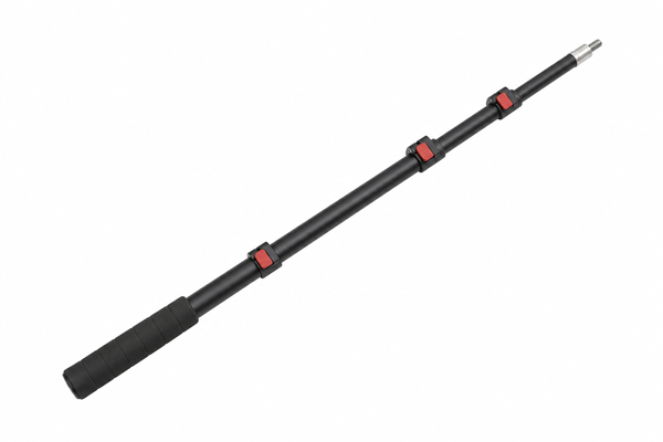
A push button lock telescopic pole must keep each section stable while allowing practical adjustment in the field. The tube, lock, grip and end interface must be specified as one system.
Xingyong develops aluminum locking poles around the intended tool head, working range, user handling and supply format.
Push Button Lock Structures
Select the indexing and button route around required working lengths, setup speed and tool interface.
Positive locking at defined positions for simple repeatable setup.
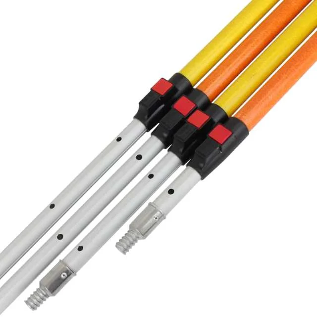
Multiple indexed positions for adjustable working lengths.
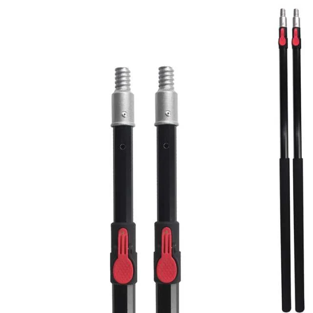
Specified button, hole spacing and connector configuration for OEM systems.
Applications
Locking poles are selected where controlled length changes and stable tool alignment matter.

The case button locks win: length is set by a hole, not by friction, so it cannot creep under load no matter how heavy the head is.
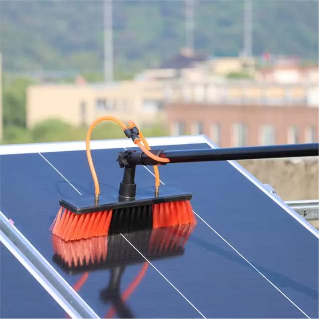
Continuous adjustment. You get the lengths the holes give you — fine for a kit sold at fixed reaches, wrong for work that needs any length in range.
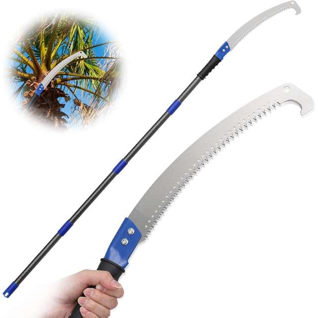
Almost every button-lock complaint is a hole-position or spring-fatigue problem, not a tube problem. Both are checked on the sample.
Why Us
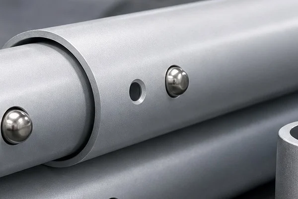
We develop the tube, section lock and connection detail around the target working condition rather than treating the lock as an isolated component.
Explore twist lock poles and flip lock poles.
Button Lock Selection
Define working positions, button force and tube indexing before confirming the button-lock pole program.
| Selection Factor | Single Button Lock | Multi-Position Button Lock | Custom Button Interface |
|---|---|---|---|
| Best for | Defined standard working length | Several repeatable working positions | Proprietary tool systems and OEM kits |
| Primary consideration | Button force and hole alignment | Hole spacing and easy position selection | Interface geometry and retention requirement |
| OEM input | Target length and tool head | Required length positions and section plan | Sample, drawing and approved fit criteria |
Push Button Lock Matching Checklist
These details help define the correct tube, section and lever-lock configuration for an OEM quotation.
The exact stop lengths your line sells on — the hole pattern is the product, and it is cheaper to agree before tooling.
The load the button must hold with the head fitted, which sets button diameter, spring rate and wall thickness at the hole.
Cycles per season and the water chemistry the spring sits in — stainless grade follows from that, not from a catalog default.
The choice depends on required adjustment, use environment, tool load and target user experience.
Yes. Send a sample or technical drawing so the interface can be reviewed.
Yes. OEM programs can include color, marking, packaging and accessory selection.
Related Products
Technical Support
Explore practical buying, specification and application guidance related to this product.
Send your target tool, reach, lock preference and packaging brief for an OEM quotation.
 English English
  Español
 Français
 Deutsch
 Português